Game Boy Advance Assembly Guide | Boxy Pixel
0.0 Before you begin
0.1 Materials needed
- Stock GBA
- Boxy Pixel Aluminum GBA Housings
- Aluminum Button Set
- Silicone Button Set (optional)
- LED Light Pipe Diffuser (optional, if need to replace original)
- IPS Screen Kit by Funnyplaying
- Glass IPS Screen
- IPS Screen Adapter - 3D Printed
- Type C Charge Board (optional)
- Micro USB/Type C Battery Housing - 3D Printed (optional)
- Boxy Pixel 2000 mAh battery
- Aluminum Shoulder Buttons (optional)
- Kapton Tape (optional)
1.0 Testing
Prior to disassembly of the donor Game Boy, insert batteries and a game cartridge. Turn the volume wheel all the way up, and switch the device on.
- Listen for a chime at startup
- Confirm that all buttons (including triggers, start, and select), function well.
- Wiggle the power switch to ensure it stays powered on

2.0 Disassemble stock Game Boy Advance
2.1 Remove the six tri-wing screws from the back housing (shown with yellow arrow). Remove the last fastener shown (red arrow), this uses a Phillips screwdriver.

2.2 Once open, remove the four fasteners holding the sheet metal to the inside of the rear housing (see red arrows). Use the smallest Phillips screwdriver. Keep this sheet metal, and dispose of the screws that you removed.

2.3 Remove the plastic power switch by pulling it up and also Remove L and R triggers. (Shown by the yellow arrows below)

2.4 Release the flex cable by carefully prying up simultaneously on the two small brown tabs (shown by red arrows). They will pop up a few millimeters. Do not pull with too much force. Once these brown tabs are in the up position, next pull up the orange flex cable to release it. (shown by the yellow arrow below)

2.5 Remove three fasteners holding the PCB with a small Phillips screwdriver. Lift up to remove the electronics (Nintendo PCB). Be careful with speaker wires, to not break the solder joints.

Be sure to not lose the small clear diffuser in the front housing-- keep this for future use. (shown by the red arrow)

2.6 Next, remove the two battery terminals. Turn over the PCB and heat the solder from the backside. Carefully push or pull the terminals out, using pliers.

2.7 Clean all gold-colored contacts with alcohol. Clean the power switch by pouring a few drops of isopropyl alcohol into the switch. Switch on/off a few dozen times and use compressed air to dry out prior to putting PCB in the shell.

2.8 Verify the aluminum shell does not have blemishes. Check for bends or distortion on the area around the screen. Verify the plastic fixture does not have any debris on the soft surfaces that could scratch the housing. Place your metal front GBA housing face down on a surface. Ideally, use an item that will raise the front surface slightly to allow the buttons to fully drop down into position. See our universal fixture that we have available for purchase.

3.0 Buttons and Silicone
3.1 Drop in your directional keypad and A/B buttons. The two buttons can only be placed in one orientation, as shown.

3.2 Next is to install the conductive silicone set. Drop in the silicone over the buttons, and D-pad, and start/select. Note: You may choose to install the original silicone on the D-pad. This has a different feel than the aftermarket ones.
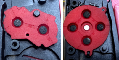
3.3 Drop in the clear diffuser at the location shown on the left. Notice the orientation rotationally.

4.0 New Screen Installation
4.1 Make the connection by carefully aligning and pressing the parts together. This flex cable area circled is VERY fragile!
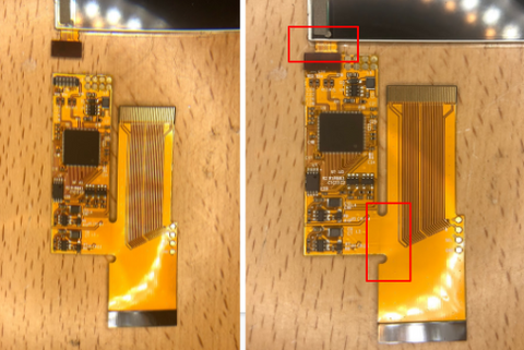
4.2 Remove the screen protector. Do your best not to touch the front surface of the screen.

4.3 Place the screen in the housing. Move it up and to the right. CAREFULLY fold the flex cable up as shown below.


4.5 Solder a thin wire to TP2 shown below. Add a small amount of solder to the gold pad first. Then introduce the wire. Do Not leave the solder iron on too long! 2-3 seconds is enough.

4.6 Add Kapton tape to help relieve strain on the wire and keep it in place.

4.6 Prepare the orange flex cable by adding solder to 3 locations. SEL, R, and L as shown at left. Do Not leave the soldering iron on too long! One second is long enough.

4.7 Solder the wire from TP2 (previously soldered to PCB) to the SEL on the orange flex cable at left.

4.8 Cut two thin wires to length. Note: Some LCD screen kits have these wires already included. Strip both wire ends.

5.0 Solder Wires to flex Cable
Add Kapton tape over whichever option you did NOT use.

5.4 Carefully begin flipping the PCB over. Ensure the orange flex is not getting trapped on top. Make sure the start/select silicone stays in place. The Flex can tear! Use caution!

5.5 Carefully continue to flip the PCB over. Connect the flex cable. Guide the two black wires such that they are out of the way.

5.6 Ensure the orange flex cable is fully seated as shown on the left. Lock the flex cable by pushing down on the two brown tabs.

6.0 Fasten PCB and Install Battery
6.1 Be sure the black wires are not being pinched. Fasten the PCB in place at the locations shown.

6.2 Solder the wire coming from the L to the location shown by the green dot. Notice the red-filled rectangles at left. These are keep-out zones for the wire routing!
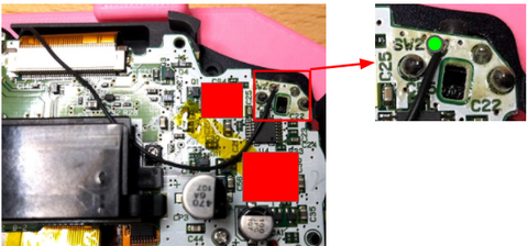
6.3 Solder the L and R Wires. Solder the wire coming from the R to the location shown by the green dot. Notice the red-filled rectangles shown at left. These are keep-out zones for the wire routing!

6.4 Review Power circuit. Next is to solder the battery, diode, and power board. At the left is a general diagram. Note the orientation of the diode. Detailed steps to follow.

6.5 Assemble Power Board. Slide the micro USB board (or type C) into the 3D printed piece.

6.6 Cut two wires and strip wire insulation.


7.0 Solder to the PCB

7.3 The diode and all wires should fit in this area denoted in red. This leaves room for the battery to sit on top.

8.0 Battery Install
8.1 Place the battery in position.

8.2 Add a THIN piece of foam to the back of the battery or the housing to prevent rattling. It is recommended to instead add this foam to the inside of the rear housing.


9.0 Final pieces
9.1 Add the triggers by sliding the metal piece down in the channel shown.
9.2 As you slide it down, compress the metal slightly to move the trigger to its final location.

9.3 Power switch install. You may need to wiggle the switch from L to R into position.

9.4 Secure Sheet Metal to Rear Housing - Set the sheet metal part previously removed from the donor GBA. Fasten in place using two 4mm long fasteners. These are shorter than the typical 6mm long fasteners.
Note the orientation of the shield.

10.0 Closing Shell

11.0 Testing
- Front button function
- Top trigger buttons function
- Screen brightness functions by holding select and simultaneously using the top trigger button
- Triggers actuate smoothly
- Sound work
11.2 Flip the Game Boy over, clean all surfaces, and install the front screen protector.
Tip: Using a humid environment can help to minimize dust caught under the front glass screen

Enjoy your newly modded Game Boy Advance!
For a printable version of this guide - click here