Backlight Your Game Boy Advance Assembly Guide | Boxy Pixel
Boxy Pixel Game Boy Advance Backlight Assembly Guide
Updated 5/23/19
The following guide is a working document that describes the basic steps necessary to transform your stock Nintendo Game Boy Advance to use a blacklit LCD (referred to AGS-101 screen).
Parts Needed:
-Nintendo Game Boy Advance
-Custom machined Game Boy Advance aluminum housings (Boxypixel)
-AGS-101 screen with adapter
-Micro USB power board or Type C Charge Board
-Custom battery holder/USB locator piece (BoxyPixel)
-Wire (26 AWG stranded) - 6" total
-Small Phillips screwdriver
-Soldering iron
-Flex cable screen adapter (40-pin or 32-pin)
Optional
-New A/B buttons/direction keypad
Dissemble the stock Game Boy Advance:
Turn it face down, and remove the battery cover and batteries. There is 1 small Philips drive screw to remove circled in red Next, remove 6 tri-wing screws from the rear of the housing, shown circled in yellow. Remove the rear cover.

Next, remove the thin sheet metal from the rear housing held by 4 Philips drive fasteners shown below circled in red.

Disconnect the old screen by releasing the flex cable. To do so, there are two small tabs that need to be pushed up ever so slightly (do not remove them). This releases the flex cable from the connector as shown below.

The flex cable is released and ready to be removed.

Next, remove the Philips drive fasteners holding the Nintendo PCB. Set the PCB aside for now.
Carefully place your aluminum front housing onto a soft surface. Inspect your AGS-101 screen, then remove the front protective plastic. Place the screen into the front housing as shown below. Avoid touching the front surface of the screen.

Drop in your A/B buttons and Directional keypad.
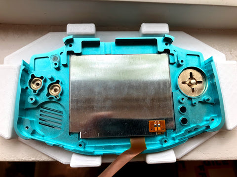
Insert the rubber silicone over the A/B buttons, and the directional keypad, and also drop in the start/select silicone. Make sure to orient your directional keypad silicone as shown.

Install the LED light pipe.
There are two scallop cuts on the sides. Rotate this clear light pipe piece until it sits flush with the fastener hole that is next to it as shown below.

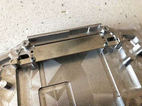
Attach the thin rear cart guide sheet metal piece using two of the included screws. You may have just started each screw a couple of threads to get both screws started, then snug (do not over-tighten) them both down. If you encounter any screw that is very difficult to go in, please be careful! The screws can snap. M2 x 6mm long screws come with the shell, however, M2x4mm long could be used if you feel too much resistance. When complete, set this aside for now.
Remove the two battery battery posts shown below.

You can remove them entirely by de-soldering, or you can just cut them as shown below if you plan to solder from the bottom.

Trim solder joints on the backside of the Nintendo PCB are shown in the areas in red below.

Although you can solder the +/- wires to the top side, I find it easier to get the solder to flow on the backside as shown below. If you use this method, I suggest routing the wires up as shown. (even more is better). This will become clear later when fitting parts together.

Attach your new flex cable adapter to the top of the Nintendo PCB connector.
There are two different flex cable sizes available. The example shown is 40 pins. Be sure to push the two brown plastic pieces down to lock the piece into place.

Next, get ready to connect the AGS-101 screen to the other end of your flex cable adapter piece. This side of the flex rotates to open. See the two images below showing the closed and then open position.


Insert the flex cable from the AGS-101 screen as shown, and close the lock tab on the flex cable back down. Your connection to the screen is now complete.

Next, wrap the flex cable around the bottom side of the PCB. In order to keep this piece from moving, I suggest taping it into place. If it moves out of position, it can press on the backside of the AGS-101 screen and create a dark spot when fully assembled.

Rotate the Nintendo PCB into the position

Be mindful of the speaker. You may have to adjust it into it's pocket.

Keep an eye on your flex cable adapter. If the tape holds, it should look similar to below. There should be extra slack in the visible flex cable shown below.

Start the fasteners to hold the PCB, but do not tighten yet. Your 3D-printed piece needs to slide under the PCB. Below are the locations of the two fasteners.


Prepare the Boxy Pixel micro USB battery holder by sliding the micro USB charging board into the 3D printed housing.

A diode must be used to reduce the voltage. The image below shows the diode inserted into the out + hole and bent. Note the orientation of the grey stripe on the diode in the image below.

Now is a good time to turn over, solder the diode, and trim the excess length shown below.


Put the assembled micro USB and holder into position in the housing.
Make sure the positive and negative wires that you previously soldered to the Nintendo PCB are out of the way. Fasten the two fasteners to hold down the micro USB holder and also tighten the two Nintendo PCB fasteners you previously left a little loose.
Solder the micro USB board and battery.
Below is an overview of all the wiring. At this step, we're just doing the battery.
Red battery wire to B+ on micro USB PCB,
Black battery wire to B- on micro USB PCB

Solder the red wire from the flex cable to the left top left leg of DA1 as shown below. Route the wire and tape. The tape shown below covers a mounting screw hole. Don't do this.

Now is a good time to turn on and try out a game, and all button functions.
Add your L and R plastic triggers. I guide the metal piece in, then guide it into position. It will stay on its own.


Install the power switch plastic into the groove in the housing.
Note: the power switch may require it to be shaved a very small amount if you find it is too tight after the front/rear are assembled. Carefully do not break the little legs on your power switch. The green area (or opposite side) may need to be shaved.

Next, set the battery into position and bring the rear housing down into position. I'd recommend adding a couple of layers of Kapton tape to the backside of the battery as it lightly touches the rear metal housing and could wear. Lastly, sometimes the triggers can move out of position slightly, so keep an eye on them.

Before securing the rear housing to the front, apply a small patch a foam to secure the battery from moving inside the completed build.

Install 4 fasteners.

Flip over, clean all surfaces to perfection, and install the front screen protector.
Tip: You may want to turn on a shower and install the screen in a somewhat steamy room as it helps to settle any dust particles that naturally float in the air. But not so humid that it forms condensation on your parts!
Note:
If you have a dark spot on your screen, then something on the inside is pressing on the backside of your AGS-101 screen. Often, it is the flex cable adapter. Another possible reason is the battery wires are bunched up under the battery. This will cause the battery to push on the 3D-printed part, which could press on the back of the screen.