Assembly Guide - Backlight Your Game Boy Color Using the AGS-101 Screen | Boxy Pixel
Updated 4/14/19
The following guide is a working document that describes the basic steps necessary to transform your stock Nintendo Game Boy Color into a custom Game Boy Color with a backlit AGS-101 screen using machined housings. If you're debating on whether or not you can do it, I encourage you to try! If you're new to soldering, get some old parts and practice. It's not as difficult as it seems!

Parts Needed:
-Nintendo Game Boy Color
-Custom machined Game Boy aluminum housings
-Backlit screen - This can be an AGS-101 or Benn Venn Freckleshack
-Adapter Electronics - Connects between the Game Boy and your new Screen
-Rechargeable Lithium battery: (DC 3.7V 1200mAh 603450 Li-ion Rechargeable Lithium Polymer will easily fit) A 2000mAh can also fit if the following battery size does not exceed the following dimensions: 51mm long x 34mm wide x 10mm thick MAX. My 2000 mAh battery on my site fits.
-Micro USB power board or Type C Charge Board
-Custom battery holder/USB locator piece (BoxyPixel)
-Replacement screen cover
-Kapton tape (Electrical tape can be made to work in a pinch)
-Wire (26 AWG stranded)
-Small phillips screwdriver
-Soldering iron
Optional
-New A/B buttons/direction keypad
-Power LED
-Black bezel or vinyl tape
-Velcro strap
Steps
Important tip! If you have a non-anodized machined aluminum housing, these raw aluminum parts must be handled with care! As such, if you lay the non-anodized aluminum shells face down on a surface with any contaminants, you can scratch the surface. It is advisable to coat the surface if you have a non-anodized housing. I have had success with a product called Protectaclear. It's durable, easy to apply, and won't yellow.
If you do get a scratch, it's not the end of the world. You can remove light scratches with a scratch-removing compound and microfiber cloth. It's much easier to do this before assembly.
Ok, now onto the assembly -> with foam or microfiber cloth on the table!
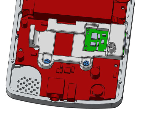
1. Carefully disassemble the stock game boy color by first removing the tri-wing screws from the back housing. Screws are circled in yellow below. Once open, remove the 4 fasteners holding the sheet metal (Shown circled in blue).

2a. The front housing has the electronics. Release the flex cable by carefully prying up simultaneously on the two tiny brown tabs. (shown by the blue arrows below). They will pop up a couple of mm and release the flex cable.
2b. Remove the fasteners holding the PCB to the front housing using a small Phillips drive, and remove the electronics. Careful with the speaker wires, so as not to break the solder joints.

3. Prepare the micro USB battery holder. Sometimes I will glue or tape the Micro USB to the battery holder to make handling easier later. Adhesive is NOT required.

4. Trim all the solder joints on the backside of the Game Boy PCB as shown below. The backside should be fairly smooth to the touch. It's important to try to get them as smooth as possible, but not damage the board. A diagonal flush cutter shown below can get them very close to flush. Using a small very fine file will get it that much smoother, just be careful and you will be fine. I have found that it is most critical to work on the pins near the LED/Nintendo link port. Make these flat flat flat!

4b. Since you have your flush cutters out, it is advisable to trim the sides of of Nintendo link port metal connector. There are two small metal wings that stick out the sides. Although possible to assemble with these there, trimming them will make assembly a little easier later. Before careful not to distort the connector itself when cutting, and use safety goggles.

7. Next, remove the stock AA battery terminals by heating them with a soldering iron near the solder joint and pulling them out with pliers. The image below shows how it should look after removal. I typically heat up on the opposite side of the board.

8. Next remove the stock front red LED by heating the two solder joints on the backside of the board with a soldering iron and pulling out. I put tension on the LED with plyers and heated up the backside solder joints.
9. This is a good time to solder the positive and negative cables to the Game Boy PCB. After soldering, trim the solder joints on the backside if they are not flat.

11. Prepare the cart shield by applying Kapton tape. Secure to rear housing using M2x6mm long fasteners (Qty 4) Tip: Check for any objectionable machining burrs or sharp edges that may interfere with inserting your game cart in and out.
Note: There are some housings that may make these fasteners very tight. These can break if you force them. You can either purchase M2x4mm long fasteners, or run a tap, or you can get the fasteners to go if you are VERY careful. If there is too much resistance, they could break so use caution! The upper to fasteners are technically not necessary as this gets held in place when assembled.

13. If desired, install an aftermarket LED into the front housing as shown below. I typically use Kapton tape to hold the LED near the center of the LED hole. (Image shown). Ensure the wire is in the channel and the tape is as flat as possible. The AGS-101 screen thickness fits very tight. You need to ensure there is only 1 layer of wrinkle-free tape.

Next, prep the adapter component that adapts the new AGS-101 screen to the Nintendo connector. Currently (as of March 2019) there is a readily available adapter from China that seems to work well. It requires wiring 3 wires for brightness control. Benn Venn is creating a similar-looking adapter that does not have brightness control, which simplifies this step. For now, solder 3 wires to 3 points on the PCB and connect the ribbon cable as shown below. The innermost wire is the longest. Read ahead to see why!

Side Note: If using a Benn Venn adapter as shown, no soldering is required for this step. Simply attach your backlit screen to the adapter PCB. You can also ignore any future steps that involve the wires soldered to the adapter PCB.

Next, connect your new backlit screen to the adapter PCB.

This is a good time to verify the function of all your components. The screen should work, and the screen will likely automatically flash from brightness from low to high. This is normal as the brightness controls are not yet connected.

Next, put the PCB in position as shown and mark where I think the ribbon cable will end up.

I taped the ribbon cable in position. This is not required, I find this a personal preference as it somewhat holds the China adapter in its proper location. Find a method that works best for you!

Drop in your directional keypad and A/B buttons. Note: I have noticed that the AGS-101 flex is very close to one of the legs of the buttons. (See white corner below). This usually doesn't seem to affect things, but I have been trimming the leg of the button just to be sure.

Install the silicone buttons. I typically trim the silicone edges that are near the Chinese adapter. This helps prevent the China PCB from interfering with the silicone later.

Next, I wire two wires from the China PCB to the backside of the Game Boy. This is again a matter of preference. I wire to the two locations shown below.


Apply Kapton tape to the backside of the PCB to cover the solder joints.

Make sure the power is off, and carefully flip the board over and connect the ribbon cable. Be mindful of your LED wires.

As you bring the board down into position, watch the cables you soldered.

And also, make sure the speaker goes down in position behind the PCB.

Below is the board in its final location. You can see a Gold circle just above the negative battery terminal (D4 on board) should be flush with the Nintendo PCB.

Hold the PCB in place, install the micro USB assembly, and secure using two M2x6mm screws as shown below.
You should now have 3 wires that need to be connected as shown below. You're almost there!

To connect the grey wire from the China PCB, I found a small place to solder. Below, the exacto knife is pointing to this location on the board. It's labeled as D2. I typically very gently scrape around this hole to expose some copper.

Then, solder this wire as shown below.

Solder red (positive +) and negative (black -) wire leads from the Nintendo PCB to the new micro USB board as shown below. (Red wire from Nintendo to out + on micro USB board. Black wire from Nintendo to out - on the micro USB board.)
Lastly, solder the battery. Make sure the Game Boy is off.
Solder the red wire from the battery to the B+ location on the micro USB board. Solder the black wire from the battery to the B- location on the micro USB board.

Set the battery in position. Make sure the wires are out of the way as shown below. It is highly recommended that several layers of Kapton tape is applied to the battery. The battery is wrapped in a very thin layer of material that can rub on the metal housings.

Next, install your new LED. The old LED location has two holes. The inner solder through the hole is negative (black). The solder hole closest to the board edge is positive (red). Solder a resister (2K ohm recommended) to the positive side. Then tape the excess wire so it does not get pinched. I like to leave it long like this so I can disassemble it later if needed.

Trim the power switch as shown below 2 images. This is the opposite side that is typically trimmed. The reason is, that you can now keep the 'snap' feeling when switching on/off.


20. Place the power switch in the rear housing. The trimmed plastic switch piece will install upside down as compared to the original Game Boy. Carefully bring the rear housing down together. As you bring it down, make sure your power switch lines up with the power switch on the Nintendo board. You could break the Nintendo power switch if they are out of position and you force the parts together.
If you're having trouble with the switch install, here is a video that hopefully will help:
21. Apply a small amount of foam to the rear housing of the Gameboy Color to ensure that the battery does not move.

22. Install M2x6mm long (qty 2) fasteners at the top two corners. Do not overtighten these tiny screws. Install M2x 6mm (qty 2) long fasteners into the deep holes.

23. Flip over, clean all surfaces to perfection, and install the front screen protector. You may want to turn on a shower and install the screen in a somewhat steamy room. This helps minimize dust under the screen.

24. Power up, and enjoy! If you'd rather have us build one for you, I can custom-mod one for you.
