Game Boy Color Assembly Guide | Boxy Pixel
Boxy Pixel Aluminum Game Boy Color Assembly Guide
Necessary
- Boxy Pixel Game Boy Color Aluminum Housings
- Either an IPS Screen or Laminated Screen
- Rechargeable Lithium Battery
- Type-C power board
- Custom battery holder/USB locator piece
- Replacement screen cover lens (Not needed if using laminated screen)
- Kapton or electrical tape
- 26 -28 AWG wire recommended
- Small Philips screwdriver
- Soldering iron
Testing
Prior to disassembly of donor Game Boy, insert batteries and a game cartridge. Turn volume wheel all the way up, turn on console. Listen for a chime at startup, then confirm that all buttons (including Start and Select) function well. Wiggle the power switch to check that the device remains powered on.

Disassemble 'Stock' Game Boy Color
Remove the six tri-wing screws from the back housing-- shown by the orange arrows below.

Once open, remove the small four Phillips drive fasteners holding the sheet metal, shown by the orange arrows below. Keep this sheet metal.


Remove the three fasteners holding the PCB to the front housing (red arrows below), using a small Phillips screwdriver. Remove the Nintendo PCB, being careful not to break any solder joints that connect the speaker to the PCB.

Remove the plastic power switch (orange arrow below). It can be removed by just pulling upward.
Remove the IR port plastic (red arrow below) also by pulling up. Keep both of these parts.

Next, we will remove the two battery terminals (arrows below).

Turn over PCB to heat the solder on the other side. This will allow you to carefully push or pull the terminals out using pliers. Careful, they get hot!

PCB Preparation
If needed, clean all gold-colored contacts with isopropyl alcohol (we used a swab dipped in alcohol to apply it). If the power switch needs to be cleaned, pour a few drops into the switch. Turn on and off a few dozen times and use compressed air to dry. Below, our PCB definitely needs a good cleaning!

Make sure the Nintendo power switch is in the off position.
Cut two wires to approximately 60mm (2.5") in length. Strip insulation at both ends of the wire. 28ga wire works well.
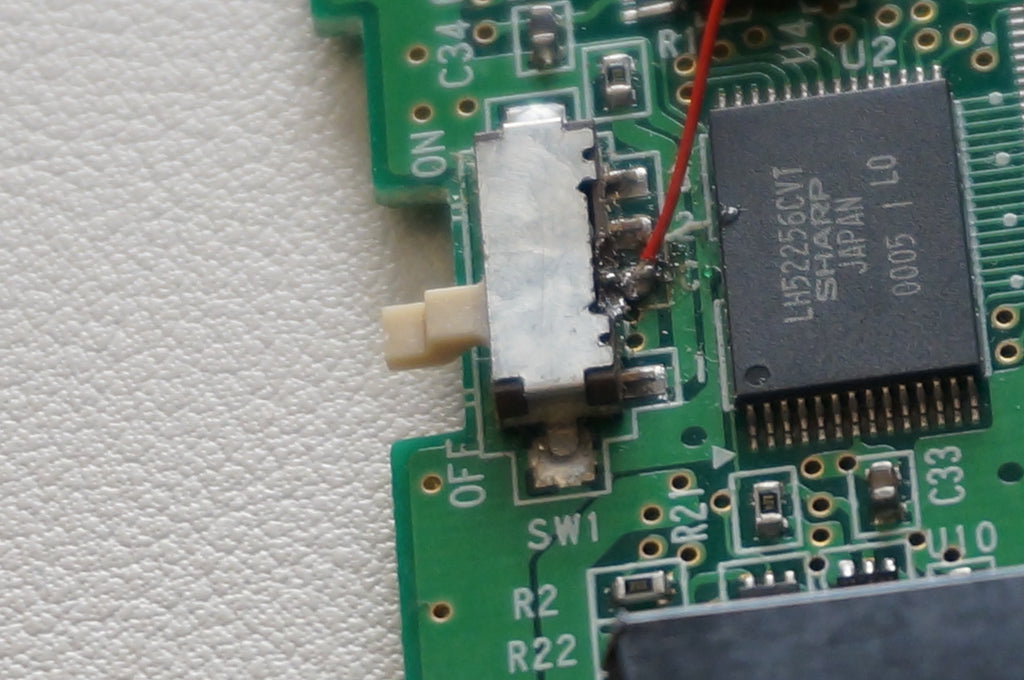
Solder one wire from the type-C board hole labeled OUT- to the Nintendo PCB Negative terminal that you previously removed. This is shown as a black wire in the below image.
Solder a second wire from the type-C board hole labeled OUT+ to the Nintendo PCB Positive terminal that you previously removed. This is also shown as a black wire in the below image.
Next solder the red wire from your 3.7V battery to the B+ hole in the type-C board.
Lastly, solder the black wire from your 3.7V battery to the B- hole in the type-C board.

You can turn on the power switch to verify everything is wired correctly. If the LED lights up and you hear the game boy 'chime", you've completed converting your Game Boy to have type-C charging.
Prepare Front Shell
Verify the your shell does not have blemishes. Check for any machining burrs or sharp edges that may interfere with inserting and removing a game cartridge. Always check that your IPS or laminated screen kit fits as intended. If you have an unfinished brass shell and want to keep it shiny - you'll need to prep and coat the brass. This is a project in itself. I would recommend consulting with the experts on youtube and take your time.
When ready for assembly, place the front housing face down.
Note: We have a universal adjustable fixture that holds the Game boy color and all other Game Boys also.

If you are using a laminated screen, see the following steps
First, do a dry fit test of the laminated screen into the housing and test the function of the screen by soldering the single power wire and installing the orange flex cable.
Solder one side of the wire to the Nintendo power switch, third pin from the top. See location shown below.
Next, solder the other end of the wire to the laminated screen electronic board. There is a spot labeled "bat" on the green pcb.

Now that the power wire is soldered, connect the screen's orange flex cable into the Nintendo PCB board.

Lock the orange flex cable into place with the two brown plastic pieces of the connector.

Turn switch on, and verify the screen works

After confirming the fit and function, you may want to desolder the power wire from the Nintendo PCB and disconnect the screen.
Prepare the doubled sided tape on the inside edges of the glass screen by removing the film (orange colored) around the inside edges of the screen.

Slide the screen back into position and gently press to adhere the screen to the front housing.

If you are using an IPS screen, proceed with the step below

Before installing the IPS screen, please test the screen as we cannot accept returns for screens that have been installed. Test by simply plug in the orange flex cable into the Nintendo connector (Red arrow below), then lock into place by pressing the brown tabs down. (two yellow arrows below). Insert a game and turn on the Game Boy Color.

After confirming your IPS screen is working properly, install the included clear plastic sticker to the backside of the LCD panel as shown below.

Next, use the included double sided adhesive strip to adhere the IPS screen to the housing. It looks like a white strip. Shown below.

Cut it to roughly fit the areas shown, then peel off one side of the white paper backing. Attach to the front housing. Firmly press in place, then remove the other white backing to expose the clear tape.

Prepare you IPS screen by peeling back the clear protection from the front of the screen. Do your best not to touch the front of the screen.

Lastly, install the screen face down into the front housing. It should look like the image below. Alternatively, if you would rather not use adhesive you could use foam on the backside of the LCD PCB board. When you install the Nintendo electronics, it will compress the foam and keep the LCD in place. Do not use a foam or material that is too rigid as you could distort the image on the screen crack the LCD.

The two wires with copper are the touch sensors. The left touch sensor is for the color palette. Since these are metal housings, we do not have a method to make this operable. We recommend removing this sensor.
The touch sensor on the right is the brightness control and will attach to the black translucent IR sensor cover.
GBC Buttons and Silicone
Drop in the directional pad and A/B buttons. The two buttons can only fit in one orientation, as shown.

Drop in the Start/Select silicone. Drop in the two other silicone pieces over buttons and D-pad.

Connect the LCD to PCB
If you have and LCD with a touch sensor, you can attach it to the plastic IR port as shown below by the yellow arrow.

You may need to devise a way to make the touch sensor work. If you cannot get the conductive touch sensor to work, you can also try drilling a hole in your IR plastic and using a fastener. Using a small pan head fastener, put the fastener through the hole and secure with a nut. Lastly, solder your touch wire to the fastener on the inside. Although it's not fancy, this is the most reliable method I have found.
PCB Installation
The screen should be in position, and the buttons with silicone installed. Now, gently move the Nintendo electronics (PCB) roughly into position. When doing so, you will need to position the speaker first. The wires connected to the speaker should be visible. I like to connect the flex cable to the PCB before the PCB is into place. (I find it easier this way). Note: If you are using a laminated screen that requires soldering a power wire, now is a good time to make the final connections if needed. (red wire shown below)

Lock the Nintendo PCB to your screen by installing the flex cable into the connector (red arrow) and then locking into place (two yellow arrows).
Before the final installation of the type-C charge board and 3d printed piece, test fit. If it doesn't sit flat, you may need to trim off one of the posts on the bottom of the 3d printed part as shown by the red arrow.

Next, hold the PCB in place, install the type-C USB board and 3D printed holder. Secure using two M2x6mm screws, as shown below.

Turn on to test.
Set the battery in position, ensure that wires are tucked out of the way. Cut and place soft foam on the battery or, preferred, inside of the rear housing. This will help to prevent the battery from moving.

Power Switch
Insert the plastic power switch back into position. You may have to move it up and down as you carefully wiggle it into position.
Caution! Small white finger that is part of the power switch on the PCB is very fragile. Keep this in mind always, especially when installing the rear housing.


Secure Sheet Metal to Rear Housing
Install the sheet metal that was removed from the plastic housing. Note the orientation of the two legs. No tape is necessary. Fasten using the included 4mm long fasteners.

Carefully bring the rear housing into position. You may have to wiggle it a bit. Using the included fasteners, install two M2x6mm long fasteners at the top of two corners. Put these in halfway.
Install two M2x6mm into the deep holes as well. Make sure housings seem to be going together well, and fasten all four fasteners.
Caution! Ensure plastic power switch is lined up. Also ensure battery and wires are out of the way before bringing down the rear housing.

Turn over the unit and confirm that everything functions by testing
- Sound
- All front facing buttons
- LED and screen are on
- Charge port is lined up

Final Touch
Flip Game Boy over, clean all surfaces, and install the front screen protector. If you're having trouble with dust, try using a humid environment to help minimize dust caught under the screen.

Enjoy your fully modified custom Game Boy Color!