DS Lite Macro Assembly Guide | Boxy Pixel
Boxy Pixel Aluminum DS Lite MACRO Assembly Guide
Updated 8/4/20
The following guide is a working document that describes the basic steps necessary to convert a broken DS Lite into a Game Boy Macro utilizing Boxy Pixel front shell.
Items Needed:
Nintendo DS Lite
Boxy Pixel Front Housing (fasteners included)
Speaker
Tri-wing Screwdriver
Soldering Iron
Aluminum Front Housing
Optional:
New buttons
Rear housing
First, using a tri-wing screwdriver, remove all visible screws on the back of the DS.

Remove the battery cover and battery.
Remove the screws underneath the battery. There is one in the bottom right corner that is a tri-wing. There are two others that are Philips.
Remove the 2 rubber caps on the top of the DS shown in the image below. Underneath should be 2 Philips drive screws; remove these.

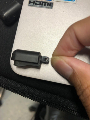
Remove the fastener near the SLOT-1.

Remove the back housing, and set it aside for later if you choose to reuse it. Tip: there is a small snap fit near the SLOT2. Pulling out slightly on the rear housing may help. Make sure that the power button and volume buttons do not get lost, as well as your shoulder buttons.

Below is how the front PCB and housing should look.

Remove your shoulder buttons, and set them aside. If you are re-using your hardware, take care not to lose the springs or posts. Below is the shoulder button (albeit dirty), spring, and pin assembly for future reference.

Remove the two wires (circled in red) and the blue piece by pulling up.

Remove the last Philips fastener

Lift the PCB out of its old plastic housing as shown below. Take care, as the LCD is still attached. Lifting it too high could tear the flex cable.

Rotate the LCD and PCB together as an assembly out and out of the way. There is one more connection between the two screen that needs to be disconnected, as shown circled in red below. Pro tip: the rubber silicone pieces behind the buttons (visible below) are sometimes in questionable condition. If possible, I recommend using the stock silicone if it's in good shape.

The PCB is now free from the housings. Prepare the DS PCB by first removing the digitizer flex cable. This will no longer be used, as the touch screen will not be used when converting to a Macro.

Cut away the connector below with wire cutters so the speaker has room to rest inside the housing.

Remove the second flex cable holding the LCD screen in. Carefully flip up the dark colored plastic piece to unlock the connection. The pull the flex cable out toward the LCD to disconnect.

To wire a speaker, two wires will be used. One wire will go from the speaker to GND on the Nintendo PCB. The other wire will go from the speaker to either SPL0 or SPR0.
Ensure that there is enough wire length so that the speaker can comfortably sit in the Boxy Pixel housing. Below is the speaker with wires connected.

Finally, solder the 330 Ohm resistor onto the board. Be careful; the resistor is very small and can easily get lost. Try melting solder onto the pads first, then take a tweezer and hold the resistor over the two globs of solder. Once heated, these globs tend to attach themselves to the resistor.
Locations on board are LED C2 and LED A2. See the red arrow below pointing to the resistor location.

The latest shells as of end of July 2020 will need the aftermarket custom Macro glass and NOT require 3D printed spacers.
You will need to remove the entire touch screen. It comes off very easily. If you have an old housing that requires 3D printed spacers, here is some info:
https://www.boxypixel.com/pages/macro-glass-lens-installation-in-boxy-pixel-aluminum-housing

Now, reattach the LCD screen's flex cable to the PCB.
Drop the buttons into the metal housing.
Remember to put the start and select buttons as well, as this can be very easy to forget. Take care to put the aluminum on a soft surface. (D-pad silicone not shown, but should be installed here)
Pro tip 1: the rubber silicone pieces behind the buttons (visible below) is sometimes questionable. If possible, I recommend using the stock silicone if it's in good shape.
Pro tip 2: Some aftermarket A/B buttons have a slightly different depth dimension. This will be evident when assembled and it takes just a little more button travel. You can add a small amount of material on the inside of the button pocket. I've used vinyl transparency paper and punched out circular discs.

Now, carefully guide the LCD into place, and drop the PCB. As you are doing so, make sure your speaker is in position and speaker wires are out of the way of your L/R trigger buttons.

Speaker shown below.

If you haven't already, re-install the module you removed earlier (shown in blue below). Ignore the red circled items.

Secure the PCB with the two screws shown below.

Install the trigger posts for the left and right shoulder buttons.
Next, prepare your triggers. The metal spring should be oriented like the pictures above before placing onto the post.

Place the triggers onto the post. Your board should look like the one above.

Prepare to install the rear housing. If you have an aftermarket rear housing, you will notice that there is a square nut missing. There is one screw that holds the battery cover piece. That one screw needs a square nut installed in the rear housing. This square nut is often in the bag of misc. hardware pieces that came with your new rear housing. Refer to your old housing to see how it slides into place. If it doesn't stay, you may need to hot glue it as a last resort.
Before placing the rear housing back on, make sure that both the volume switch and the power switch are correctly aligned with the plastic!! If not, the power switch on the PCB can easily break! Once the rear housing is sitting on top of the front housing, place the battery back in place.

Next, place the battery cover over the batter, and screw it in place.

Secure the rear housing by placing screws at the points noted above. I have found when using some aftermarket housings that installing the top two screws can (not always) cause the triggers to bind. Not installing them is ok since the aluminum is so stiff.

Install the lens, and you’re done!
Tip: If you have a black or dark-colored shell, you may be able to see the silver LCD in the crack when the glass screen is installed. Use a sharpie before the glass lens is installed to color the metal on the LCD that may show.
