Right Joy-Con Switch Assembly | Boxy Pixel
Boxy Pixel Aluminum Joy Con Shells - RIGHT Assembly Guide
This is a working document, describing the basic steps to install Joy-Con electronics into Boxy Pixel metal housings.
Items Needed:
- OEM Joy-Cons with all internal parts
- Boxy Pixel metal Joy-Con housing set with fasteners
- there are varying fastener lengths, but they are all the same thread (2mm, 3mm, and 5mm)
- Your kit may include more fastener options
- Tri-wing screwdriver
- Phillips screwdriver
- Button set
- Boxy Pixel metal button set or aftermarket plastic button kit including D-pad
Warning!
Please take extra care with the fasteners-- the heads and threads are very small. You will see in this guide (and receive) fastener lengths that we have found to work well, but you will need to use your best judgment when determining which ones to use.
- When assembling, do not force the fastener! If you feel resistance, re-evaluate your fastener length or back out, clean, and try again
- Choosing the correct fastener is a balance between having a safe amount of thread engagement and avoiding using a fastener that is too long (this will risk breakage and stripping). Take your time and reference these directions for guidance. There may be times when you need to choose a differently-sized fastener than the install directions if a threaded hole is too shallow.
- The longest 5 mm fastener is the biggest risk-- although you may be able to fit this into many holes, I would only recommend installing these where the other fasteners have been found to be too short
- Fastening is NOT like the fasteners used when screwing together plastic parts. Fastening plastic parts requires extra effort as you are cutting threads in the plastic.
These metal parts already have very fine aluminum threads. They require very little force and should have minimum resistance when turning. If you are not confident in your ability to feel when a fastener is stripping, we offer a build service. That said, the next slide are rules for fastener installation. - Ensure you have the correct size of screwdriver, this does make a difference.
- For all fasteners, make sure parts are well-aligned before screwing together
- Ensure parts are fully seated and held in place when fastening. I recommend against using the fastener to pull the parts together-- this is especially important when fastening the front and rear housings.
- When starting a screw, I will often turn in counterclockwise to start. You should "feel" when the screw catches the first thread. Then, I gently turn clockwise. If you feel any resistance, stop and reevaluate. Personally, I use my fingertips to turn the screwdriver while applying enough downward pressure to keep the driver engaged. If you are stripping the screw head - you have far too much resistance and/or the incorrect driver.
- Whenever you have more than one screw to attach two parts together - always start all screws first.
- Keeping the above rules above in mind, I first would carefully choose your screws and then do a practice run for the 4 screws that hold the front and rear housings together.
- Last note, when doing the right controller, the bottom sensor is sandwiched in between the front/rear housing. There is a hole in this sensor in which the 5mm housing fastener passes through. This is a 5mm fastener location. The sensor has some intentional wiggle room to move so you need to make sure the hole in the sensor lines up with the hole in the housing. This may require some wiggling of the sensor when inserting the fastener. Otherwise, you may get an artificial increased resistance when trying to turn the 5mm long fastener.
DISASSEMBLY
Remove the 4 tri-wing screws from the rear housing. Lift off the rear housing, there are some plastic tabs that may require extra effort.

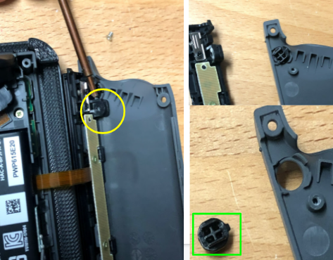
Remove this Phillips screw from the rear housing, separate the black connector piece from the grey rear housing. Keep the plastic button!
Remove 3 Phillips drive screws, then life out the antenna piece.

Begin to remove the battery/battery holder piece.

Disconnect the red and white battery wire from the PCB.
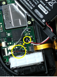
Remove the 4 Phillips drive screws (circled in yellow).

If not done already, rotate the battery/battery holder piece out of the way

The rumble motor (white piece) is held in place by adhesive on the underside. Carefully pry or lift this out of place.

Begin to lift all loose parts out of the way. Lift out the joystick.

Begin lifting the sensor. Lift all loose parts out of the way. There is adhesive on the ribbon cable, so carefully pry it up.

It should look like this when sensor is fully removed.

Carefully remove this piece, it is held in place by adhesive.

Remove all the parts as an assembly.

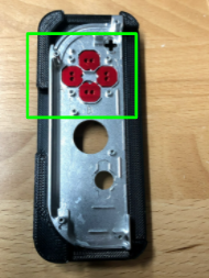
Remove all the silicone parts in the 3 following locations:

Remove all the plastic buttons.
Do not use old fasteners in metal parts.

Notes:
Take note of the new replacement fasteners. There should be 3 sizes, which I recommend sorting by length and labeling each set by size.
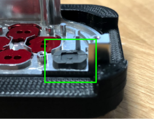
You may also want to consider chamfering your B button before installation. Take a fine metal file and make the edge of the button look like the image shown-- these silver edges are chamfered (rounded). This makes them move a bit more smoothly within the housing.

ASSEMBLY
Install the A, B,X, and Y buttons as shown. Note: It is helpful to elevate the housing to provide clearance for the buttons.
Install the silicone pads over the buttons.

Install the home button plastic.

Install the home rubber piece-- note the orientation relative to the shell.

Install the "+" sign plastic piece and corresponding rubber on top. Ensure the rubber sits correctly over the edges.
Ensure all three rubber pieces are in place. Their edges can move out of position.

Optional, but recommended:
Add very very thin double-sided tape to the backside of the metal buttons. Carefully install the rubber over the buttons. This is to ensure the buttons do not rotate and ensures they always actuate freely.
Rotate the flat antenna piece into position.

Set the sensor into position.

Begin to rotate the PCB, joystick, and rumble module into position.

After ensuring the rubber parts stay in place, secure the PCB with two 2mm fasteners shown.

Secure the joystick using two 3mm long fasteners.

Place the rumble module into the housing.

Rotate the plastic battery/battery holder piece as shown


Fold over as if closing a book


Keep an eye on this thin orange flex cable!

Make sure this antenna is out of the way:

Connect the red/white wire battery cable

It connects by simply pushing down into place

Place the R shoulder button into place


Again, check the antenna routing as you bring the battery/battery holder down

Ensure parts are fully seated into position

Install two 3mm long fasteners Note: lower fastener intentionally not installed

Test that the shoulder buttons move smoothly

Route the grey antenna wire in the channel as shown above

Slide the antenna PCB into position as shown

Prepare the rear metal housing and the black plastic release button

Install the black button by orienting the tab to the right as shown

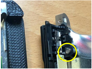
Bring the connector piece to the metal housing over the button. Install a 2mm (or 3mm) long screw circled in yellow.
Install the rear housing with the remaining fasteners. 3mm long fasteners will fit most locations. The longest (5mm) is there in the event they are too short in a certain location. Take care not to force or strip any fastener!
Tip: push the front and rear housings together, then turn the fastener. This reduces galling, reduces stress on the threads, and helps prevent stripping.
Verify all buttons move freely.
For a printable version of this guide - click here